

Class: Senior Secondary School 2 (SS2 / SSS2)
Term: 1st Term
Week: 2
Age: 16 years
Duration: 45 minutes
Subject: Basic Electronics
Curriculum Theme: Basic Electricity and Circuits
Previous Lesson: Alternating Current: Capacitive Reactance, Inductive Reactance and Impedance.
Topic: ALTERNATING CURRENT
Subject Matter: Meaning of ALTERNATING CURRENT, RL circuits, RC circuits, RLC circuits, Symbols, units, abbreviations.
Specific Objectives
By the end of the lesson, pupils should be able to:
Cognitive Domain:
- Define alternating current (AC).
- Explain the characteristics of RL, RC, and RLC circuits.
- Identify common circuit symbols for resistors, inductors, and capacitors.
- State the units and abbreviations used for resistance, inductance, capacitance, reactance, and impedance.
Affective Domain:
- Appreciate the importance of AC circuits in electronic devices.
- Develop an interest in understanding how different circuit components interact.
Psychomotor Domain:
- Draw simple diagrams for RL, RC, and RLC series circuits.
- Calculate the impedance of simple RL and RC series circuits.
Social Domain:
- Participate actively in class discussions about AC circuits.
Reference Materials
The following resources were used in planning this lesson:
- Senior Secondary Schools Education Curriculum
- State Unified Scheme of Work
- New System Physics for Senior Secondary Schools, Book 2
- https://www.allaboutcircuits.com/textbook/alternating-current/chpt-3/rl-and-rc-circuits/
- https://www.electronics-tutorials.ws/accircuits/series-rlc.html
Instructional Materials
The teacher will teach this lesson with the aid of:
- Calculator
- Resistors
- Inductors
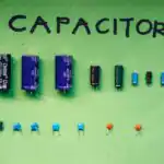
- Capacitors
- AC source
- Circuit diagrams (printed or drawn on board)
Rationale for the Lesson
Understanding alternating current (AC) and its interaction with resistors, inductors, and capacitors is important because these form the basis of many electronic systems, from power distribution to communication devices. This knowledge helps pupils grasp how everyday electronics function.
Prerequisite/Previous Knowledge
Pupils should have basic knowledge of direct current (DC), Ohm’s Law, and common electrical components like resistors, inductors, and capacitors.
Lesson Content/Board Summary
ALTERNATING CURRENT AND RLC CIRCUITS
1. Meaning of Alternating Current (AC)
Alternating current (AC) is an electric current which periodically reverses direction, in contrast to direct current (DC) which flows only in one direction. AC is the form of electric power delivered to businesses and residences, and it is the form of electrical energy that consumers typically use when they plug kitchen appliances, televisions, and lamps into a wall outlet.
2. Components in AC Circuits
The main passive components in AC circuits are:
- Resistor (R): Opposes current flow, dissipating energy as heat. Its opposition is called Resistance.
- Inductor (L): Stores energy in a magnetic field. Its opposition to AC is called Inductive Reactance (XL).
- Capacitor (C): Stores energy in an electric field. Its opposition to AC is called Capacitive Reactance (XC).
3. RL Circuits (Resistor-Inductor Circuits)
An RL circuit is an electrical circuit consisting of a resistor and an inductor connected in series or parallel. In a series RL circuit, the total opposition to current flow is called Impedance (Z).
Formulas:
- Inductive Reactance: XL = 2πfL
- Impedance: Z = √(R2 + XL2)
Where:
- R = Resistance (Ohms, Ω)
- L = Inductance (Henrys, H)
- f = Frequency (Hertz, Hz)
- XL = Inductive Reactance (Ohms, Ω)
- Z = Impedance (Ohms, Ω)
Example 1: A series RL circuit has a resistance of 30 Ω and an inductance of 0.2 H. If the circuit operates at a frequency of 50 Hz, calculate the impedance of the circuit.
Solution:
Step 1: Identify given values.
- R = 30 Ω
- L = 0.2 H
- f = 50 Hz
Step 2: Calculate Inductive Reactance (XL).
- XL = 2πfL
- XL = 2 × 3.142 × 50 Hz × 0.2 H
- XL = 62.84 Ω
Step 3: Calculate Impedance (Z).
- Z = √(R2 + XL2)
- Z = √(302 + 62.842)
- Z = √(900 + 3948.86)
- Z = √(4848.86)
- Z ≈ 69.63 Ω
Therefore, the impedance of the circuit is approximately 69.63 Ω.
4. RC Circuits (Resistor-Capacitor Circuits)
An RC circuit is an electrical circuit consisting of a resistor and a capacitor connected in series or parallel. In a series RC circuit, the total opposition to current flow is called Impedance (Z).
Formulas:
- Capacitive Reactance: XC = 1 / (2πfC)
- Impedance: Z = √(R2 + XC2)
Where:
- R = Resistance (Ohms, Ω)
- C = Capacitance (Farads, F)
- f = Frequency (Hertz, Hz)
- XC = Capacitive Reactance (Ohms, Ω)
- Z = Impedance (Ohms, Ω)
Example 2: A series RC circuit has a resistance of 40 Ω and a capacitance of 100 μF. If the circuit operates at a frequency of 50 Hz, calculate the impedance of the circuit.
Solution:
Step 1: Identify given values and convert units.
- R = 40 Ω
- C = 100 μF = 100 × 10-6 F
- f = 50 Hz
Step 2: Calculate Capacitive Reactance (XC).
- XC = 1 / (2πfC)
- XC = 1 / (2 × 3.142 × 50 Hz × 100 × 10-6 F)
- XC = 1 / (0.03142)
- XC ≈ 31.83 Ω
Step 3: Calculate Impedance (Z).
- Z = √(R2 + XC2)
- Z = √(402 + 31.832)
- Z = √(1600 + 1013.14)
- Z = √(2613.14)
- Z ≈ 51.12 Ω
Therefore, the impedance of the circuit is approximately 51.12 Ω.
5. RLC Circuits (Resistor-Inductor-Capacitor Circuits)
An RLC circuit is an electrical circuit consisting of a resistor, an inductor, and a capacitor connected in series or parallel. In a series RLC circuit, the total opposition to current flow is called Impedance (Z).
Formula for Impedance:
- Z = √(R2 + (XL – XC)2)
Note: When XL = XC, the circuit is said to be at resonance, and the impedance is minimum (Z = R).
6. Common Circuit Symbols
These are standard graphical representations:
- Resistor: A zig-zag line (or a rectangle for European standard).
- Inductor: A coiled line (like a spring).
- Capacitor: Two parallel lines (one straight, one curved for polarized; both straight for non-polarized).
- AC Voltage Source: A circle with a sine wave inside.
7. Units and Abbreviations
The following are commonly used:
- R – Resistance (Unit: Ohm, Ω)
- L – Inductance (Unit: Henry, H)
- C – Capacitance (Unit: Farad, F)
- XL – Inductive Reactance (Unit: Ohm, Ω)
- XC – Capacitive Reactance (Unit: Ohm, Ω)
- Z – Impedance (Unit: Ohm, Ω)
Teaching Methods/Instructional Techniques
Discussion, Lecture, Demonstration, Question and Answer, Visual Aids
Instructional Procedures
Step 1: Introduction
Time: 5 minutes
Teaching Skill: Set Induction
Teacher’s Activity: The teacher greets the pupils and asks them to recall what alternating current (AC) is and how it differs from direct current (DC).
Pupils’ Activity: Pupils respond by defining AC and stating its difference from DC.
Learning Point: Pupils recap previous knowledge on alternating current.
Step 2: Explanation of RL Circuits
Time: 8 minutes
Teaching Skill: Explanation/Demonstration
Teacher’s Activity: The teacher explains what an RL circuit is, its components, and introduces the concepts of inductive reactance (XL) and impedance (Z) with their formulas. The teacher also draws a simple series RL circuit diagram.
Pupils’ Activity: Pupils listen attentively, copy notes, and observe the circuit diagram.
Learning Point: Pupils understand the definition and basic characteristics of RL circuits.
Step 3: Explanation of RC Circuits
Time: 8 minutes
Teaching Skill: Explanation/Demonstration
Teacher’s Activity: The teacher explains what an RC circuit is, its components, and introduces the concepts of capacitive reactance (XC) and impedance (Z) with their formulas. The teacher also draws a simple series RC circuit diagram.
Pupils’ Activity: Pupils listen, copy notes, and observe the circuit diagram.
Learning Point: Pupils understand the definition and basic characteristics of RC circuits.
Step 4: Explanation of RLC Circuits
Time: 5 minutes
Teaching Skill: Explanation
Teacher’s Activity: The teacher explains what an RLC circuit is, its components, and introduces the formula for its impedance, briefly mentioning resonance.
Pupils’ Activity: Pupils listen and take notes.
Learning Point: Pupils understand the definition and basic characteristics of RLC circuits.
Step 5: Demonstration of Symbols, Units, and Abbreviations
Time: 5 minutes
Teaching Skill: Visual Aids/Identification
Teacher’s Activity: The teacher displays or draws the common circuit symbols for resistors, inductors, capacitors, and AC sources. The teacher also lists and explains the units and abbreviations for R, L, C, XL, XC, and Z.
Pupils’ Activity: Pupils observe the symbols and copy the units and abbreviations.
Learning Point: Pupils can identify and understand the symbols, units, and abbreviations used in AC circuits.
Step 6: Worked Examples
Time: 5 minutes
Teaching Skill: Problem Solving/Application
Teacher’s Activity: The teacher guides pupils through the worked examples for RL and RC circuits provided in the board summary, explaining each step.
Pupils’ Activity: Pupils follow the steps, ask questions, and solve the examples in their notebooks.
Learning Point: Pupils practice calculating impedance for RL and RC circuits.
Step 7: Evaluation/Review
Time: 5 minutes
Teaching Skill: Questioning/Assessment
Teacher’s Activity: The teacher evaluates the learning by asking the following questions:
- Define alternating current (AC).
- List the three main passive components found in AC circuits.
- State the formula for inductive reactance (XL) and capacitive reactance (XC).
- Identify the unit for impedance (Z) and inductance (L).
- Draw the circuit symbol for an inductor and a capacitor.
Pupils’ Activity: Pupils answer orally and in writing.
Learning Point: Pupils demonstrate understanding of the lesson.
Step 8: Conclusion
Time: 4 minutes
Teaching Skill: Summarization/Assignment
Teacher’s Activity: The teacher summarizes the key points of the lesson and gives pupils an assignment to find real-world applications of RL, RC, and RLC circuits.
Pupils’ Activity: Pupils copy the assignment and prepare for the next lesson.
Learning Point: Pupils consolidate their learning and apply knowledge to real-world contexts.
Lesson Keywords
- Alternating Current (AC) – Electric current that periodically reverses direction.
- RL Circuit – An electrical circuit consisting of a resistor and an inductor.
- RC Circuit – An electrical circuit consisting of a resistor and a capacitor.
- RLC Circuit – An electrical circuit consisting of a resistor, an inductor, and a capacitor.
- Inductive Reactance (XL) – The opposition of an inductor to alternating current.
- Capacitive Reactance (XC) – The opposition of a capacitor to alternating current.
- Impedance (Z) – The total opposition to current flow in an AC circuit.
Differentiation
For fast learners, the teacher can provide additional complex problems involving parallel RL/RC circuits or phase angles. For slow learners, the teacher will provide simplified diagrams and extra guidance on unit conversions and formula application, focusing more on conceptual understanding than complex calculations.
Note for teachers using this lesson plan
Ensure that pupils have a clear understanding of basic AC concepts before delving into circuit analysis. Emphasize the practical applications of these circuits to make the lesson more engaging. Encourage questions and active participation from all pupils.

Community Join the conversation Open discussion +