

Class: Senior Secondary School 1 (SS1, SS 1, SSS1, SSS 1)
Term: 2nd Term
Week: 5
Age: 15 years
Duration: 45 minutes
Subject: Basic Electricity
Curriculum Theme: Basic Electricity
Previous Lesson: Inductance: Series and Parallel Connections.
Topic: REACTANCE AND IMPEDANCE
Subject Matter: definition of capacitive reactance, definition of inductive reactance, definition of impedance, relationship between impedance and reactance, comparison of capacitive and inductive reactance in circuits
Specific Objectives
By the end of the lesson, pupils should be able to:
Cognitive Domain:
- Define capacitive reactance.
- Define inductive reactance.
- Define impedance.
- Explain the relationship between impedance and reactance in AC circuits.
- Compare capacitive and inductive reactance in AC circuits.
Affective Domain:
- Appreciate the importance of reactance and impedance in AC circuit analysis.
- Show willingness to learn more about AC circuit components.
Psychomotor Domain:
- Draw simple AC circuit diagrams showing components with reactance.
- Calculate simple values of reactance and impedance.
Social Domain:
- Collaborate with peers to solve simple problems involving reactance and impedance.
Reference Materials
The following resources were used in planning this lesson:
- 9 Years Basic Education Curriculum for Basic Technology (Senior Secondary School)
- State Unified Scheme of Work for Basic Electricity SSS 1
- Basic Electricity for Senior Secondary Schools by A. O. Oyenuga
Instructional Materials
The teacher will teach this lesson with the aid of:
- AC circuit diagrams
- Charts illustrating reactance and impedance concepts
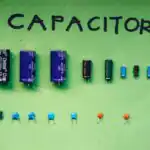
- Samples of resistors, capacitors, and inductors
Rationale for the Lesson
This lesson helps pupils understand how different components behave in alternating current (AC) circuits. Knowing about reactance and impedance is important for analyzing and designing electrical systems that use AC power in daily life.
Prerequisite/Previous Knowledge
Pupils are expected to have prior knowledge of basic AC circuits, properties of resistors, capacitors, and inductors, and the concept of frequency.
Lesson Content/Board Summary
REACTANCE AND IMPEDANCE
Capacitive Reactance (XC)
Capacitive reactance is the opposition offered by a capacitor to the flow of alternating current (AC). It is measured in Ohms (Ω).
The formula for capacitive reactance is:
- XC = 1 / (2πfC)
Where: f = frequency (Hertz), C = capacitance (Farads).
Inductive Reactance (XL)
Inductive reactance is the opposition offered by an inductor to the flow of alternating current (AC). It is also measured in Ohms (Ω).
The formula for inductive reactance is:
- XL = 2πfL
Where: f = frequency (Hertz), L = inductance (Henries).
Impedance (Z)
Impedance is the total opposition to current flow in an alternating current (AC) circuit. It combines the effects of resistance (R) and reactance (XL or XC). Impedance is measured in Ohms (Ω).
For a series RLC circuit, the formula for impedance is:
- Z = √(R² + (XL – XC)²)
Where: R = resistance, XL = inductive reactance, XC = capacitive reactance.
Relationship between Impedance and Reactance
Impedance is the vector sum of resistance and reactance in an AC circuit. Reactance (either inductive or capacitive) contributes to the overall impedance, determining how much current flows for a given voltage.
Comparison of Capacitive and Inductive Reactance
The following are key differences between capacitive and inductive reactance:
- Frequency Dependence: Capacitive reactance (XC) decreases as frequency increases, while inductive reactance (XL) increases as frequency increases.
- Phase Shift: In a purely capacitive circuit, current leads voltage by 90°. In a purely inductive circuit, current lags voltage by 90°.
- DC Behaviour: Capacitors block DC (infinite XC at f=0), while inductors act as short circuits to DC (zero XL at f=0).
Teaching Methods/Instructional Techniques
Discussion, Lecture, Demonstration, Question and Answer, Visual Aids
Instructional Procedures
Step 1: Introduction
Time: 5 minutes
Teaching Skill: Set Induction
Teacher’s Activity: The teacher greets the pupils and reviews the previous lesson on basic AC circuits and components. The teacher then introduces the topic “Reactance and Impedance” by asking pupils if they know how capacitors and inductors behave in AC circuits differently from resistors.
Pupils’ Activity: Pupils respond to the teacher’s questions and listen attentively to the introduction.
Learning Point: Pupils recall previous knowledge and are prepared for the new topic.
Step 2: Definition of Capacitive Reactance
Time: 7 minutes
Teaching Skill: Explanation/Definition
Teacher’s Activity: The teacher defines capacitive reactance, explains its formula (XC = 1 / (2πfC)), and clarifies the relationship between capacitive reactance, frequency, and capacitance using a chart or diagram.
Pupils’ Activity: Pupils listen, observe the chart, and take notes. They may ask questions for clarification.
Learning Point: Pupils understand the definition and formula for capacitive reactance.
Step 3: Definition of Inductive Reactance
Time: 7 minutes
Teaching Skill: Explanation/Definition
Teacher’s Activity: The teacher defines inductive reactance, explains its formula (XL = 2πfL), and clarifies the relationship between inductive reactance, frequency, and inductance using a chart or diagram.
Pupils’ Activity: Pupils listen, observe the chart, and take notes. They may ask questions for clarification.
Learning Point: Pupils understand the definition and formula for inductive reactance.
Step 4: Definition of Impedance
Time: 7 minutes
Teaching Skill: Explanation/Elaboration
Teacher’s Activity: The teacher defines impedance as the total opposition to current in an AC circuit, combining resistance and reactance. The teacher introduces the general formula for impedance in a series RLC circuit (Z = √(R² + (XL – XC)²)).
Pupils’ Activity: Pupils listen, write down the definition and formula, and ask questions.
Learning Point: Pupils understand the concept of impedance and its general formula.
Step 5: Relationship between Impedance and Reactance
Time: 7 minutes
Teaching Skill: Interrelation/Demonstration
Teacher’s Activity: The teacher explains how impedance is the vector sum of resistance and reactance. The teacher may use simple examples to illustrate how XL and XC combine with R to form Z, possibly drawing simple phasor diagrams.
Pupils’ Activity: Pupils observe the examples, ask questions, and take notes on the relationship.
Learning Point: Pupils grasp how reactance contributes to the overall impedance of an AC circuit.
Step 6: Comparison of Capacitive and Inductive Reactance
Time: 5 minutes
Teaching Skill: Comparison/Analysis
Teacher’s Activity: The teacher leads a discussion comparing capacitive and inductive reactance, focusing on their dependence on frequency, phase relationships, and behaviour with DC current. The teacher uses the chart of reactance to highlight differences.
Pupils’ Activity: Pupils participate in the discussion, noting the key differences between the two types of reactance.
Learning Point: Pupils can differentiate between capacitive and inductive reactance.
Step 7: Evaluation/Review
Time: 5 minutes
Teaching Skill: Questioning/Assessment
Teacher’s Activity: The teacher evaluates the learning by asking the following questions:
- Define capacitive reactance.
- State the formula for inductive reactance.
- What is impedance in an AC circuit?
- How does capacitive reactance change with increasing frequency?
- Mention two differences between inductive and capacitive reactance.
Pupils’ Activity: Pupils answer orally and in writing.
Learning Point: Pupils demonstrate understanding of the lesson.
Step 8: Conclusion
Time: 2 minutes
Teaching Skill: Summarization
Teacher’s Activity: The teacher summarizes the key points of the lesson, reiterating the definitions of capacitive reactance, inductive reactance, and impedance, and their importance in AC circuits. The teacher then gives homework, which includes solving simple problems on calculating XC, XL, and Z.
Pupils’ Activity: Pupils listen to the summary and copy down the homework.
Learning Point: Pupils have a reinforced understanding of the lesson and an assignment to practice.
Lesson Keywords
- Reactance – The opposition to current flow in an AC circuit due to capacitance or inductance.
- Capacitive reactance (XC) – Opposition to AC current flow offered by a capacitor.
- Inductive reactance (XL) – Opposition to AC current flow offered by an inductor.
- Impedance (Z) – The total opposition to current flow in an AC circuit, combining resistance and reactance.
- Frequency (f) – The number of cycles per second of an alternating current.
Differentiation
For pupils who are struggling, the teacher will provide simplified examples and focused individual attention. Advanced pupils will be challenged with more complex circuit problems involving multiple components or asked to research practical applications of impedance matching.
Note for teachers using this lesson plan
Ensure that pupils have a strong grasp of basic AC concepts before introducing reactance and impedance. Use clear diagrams and real-life analogies to make abstract concepts more concrete. Encourage questions and collaborative problem-solving.
Community Join the conversation Open discussion +